
Cooling System Configurations
Each generator set manufacturer offers different cooling system design options. The two most common types are closed-loop and open-loop systems. Closed-loop systems incorporate pumps, fans, and radiators located on a skid, creating an all-in-one unit, with container and trailer options also available.
These systems use an ethylene glycol-based coolant, which circulates through various components. Below are three common cooling system configurations:
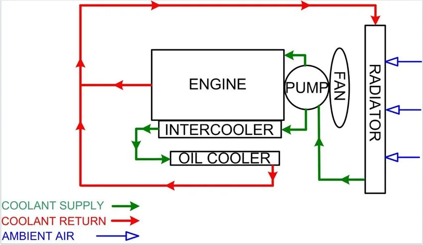
1. Single Pump Single Loop (SPSL)
SPSL systems are typically used in smaller to mid-size generators. Here’s how the system operates:
- Engine starts, and the direct-drive pump is activated, with the fan clutch rotating.
- Engine reaches operating temperature, the coolant thermostat opens, and the fan clutch engages.
- Coolant is supplied to the engine block and cylinder head, as well as internal components like the oil cooler and intercooler.
- Air is pulled through the radiator.
- Return coolant flow is directed to the radiator.
Figure-1.JPG
Figure 1: SPSL Cooling System Configuration
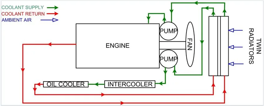
2. Double Pump Double Loop (DPLP)
DPLP configurations are typically found in larger generators or in environments with high ambient temperatures. Here’s how it works:
- Engine starts, and the direct-drive pump is activated, with the fan clutch rotating.
- Engine reaches operating temperature, the coolant thermostat opens, and the fan clutch engages.
- One pump routes coolant to the engine block and cylinder head.
- The other pump routes coolant to internal components like the oil cooler and intercooler.
- Air is pulled through the radiator.
- Return coolant flow is directed to the individual radiators.
Figure-2.JPG
Figure 2: DPLP Cooling System Configuration
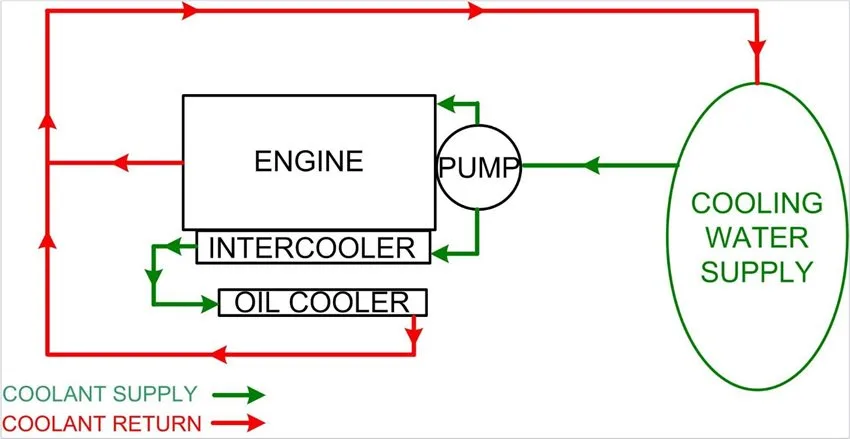
3. Open Loop (SPSL)
Open-loop systems are generally used in marine applications or in any area where an acceptable body of water is available. Here’s how it operates:
- Engine starts, and the direct-drive pump begins supplying seawater to the thermostat.
- Engine reaches operating temperature, the seawater thermostat opens, and the seawater flows through the engine block, cylinder head, and components such as the oil cooler and intercooler.
- Return seawater is routed back to the water source.
Figure-3.JPG
Figure 3: Open Loop (SPSL) Cooling System Configuration
Maintaining the Cooling System
To ensure optimal generator performance, understanding the components of the cooling system is critical. Each generator manufacturer provides their own inspection and maintenance procedures, but here are some general industry standards (always refer to manufacturer specifications):
WARNING
- Always tag and lock out all engine/generator power before performing cooling system maintenance.
- Do not remove the pressure cap from a hot engine. Wait until the engine temperature is below 120°F (50°C) before opening it to avoid steam or heated coolant spray, which can cause injury.
- Coolant is toxic. Keep away from children and pets and dispose of it in accordance with local environmental regulations.
- Do not straighten a bent fan blade or continue using a damaged one. A damaged fan can fail during operation and cause injury or property damage.
CAUTION
- The cooling system must be filled properly to prevent air locks. Air in the system can cause pump cavitation, resulting in premature pump wear and engine damage. Always refer to manufacturer’s manuals when servicing cooling systems.
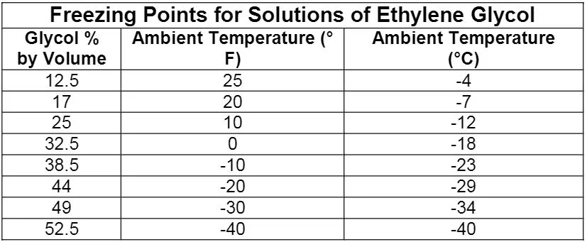
Coolant
Engine coolant is a mixture of high-quality water and ethylene glycol antifreeze. Never run water-only coolant—it’s important for coolant to lubricate the pump bearings and protect the engine from rust buildup. Always follow the manufacturer’s recommended coolant mixture specifications. Below is a table for mixing coolant to manufacturer specifications:
Figure-4.JPG
Cooling System Components
Each generator cooling system configuration will have specific components, but here’s a general list of parts you’ll find in most systems:
- Coolant Pump: Circulates coolant throughout the system and may be driven by a belt or gear, depending on engine size.
- Radiator: Can be single or twin design. Using two radiators allows for greater cooling capability in two-loop systems.
- Fan: Can be belt or direct drive. Belt-driven fans may use a clutch for on-demand engagement.
- Engine Oil Cooler: A coolant-supplied vessel with a tube bundle immersed in coolant, through which oil flows to be cooled.
- Intercooler: Coolant is supplied to a tube-and-fin bundle, located in a vessel where air flows through and cools the coolant.
- Louvers: These are used in canopies and mobile units to allow air to flow through the radiator. They may be controlled by advanced systems to open as needed for optimal performance.
Cooling System Inspections
Perform general cooling system inspections during both shutdown and operation. Always refer to the manufacturer’s recommendations for specific guidance. Below are some basic checks:
During Shutdown:
- Check for leaks at the water pump weep hole.
- Inspect the radiator for damage, leaks, and debris.
- Check coolant levels and look for oil contamination (oil in coolant may indicate a leaking oil cooler).
- Measure coolant specific gravity.
- Inspect for damage to fan, fan shroud, or belts.
- Check coolant leaks at hose connections.
- Look for coolant contamination in oil (milky oil could indicate a head gasket leak).
- Ensure louvers are closed during downtime.
- Confirm that the automatic transfer switch is in the correct position.
During Operation:
- Monitor engine coolant temperature.
- Before coolant reaches operating temperature, ensure that the fan is not spinning on fan clutch applications.
- Once the coolant reaches operating temperature, confirm the fan is spinning in fan clutch systems.
- Inspect for coolant leaks at the radiator and hose connections.
- Watch for coolant vapor in the exhaust, which may indicate a coolant leak in the combustion chamber.