Diesel engine generator governors are sometimes referred to as the speed controller for the diesel engine. The diesel engine must maintain a pre-determined speed to maintain generator output specifications. If the engine speed is not correct, the generator will not maintain the required output specifications.
This article will explore the different types of governors equipped on diesel generator sets.
Governors Can Be Divided into Two Basic Groups
- Mechanical/Electrical Control – Older generator sets utilize these control systems. The fuel system is controlled by a mechanical governor.
- Electronic Control – Newer generator sets use an electronic control system. This system interfaces and controls engine and generator control functions to provide a constant, reliable power source.
Mechanical/Electrical Control
Mechanical/Electrical Control systems were the first control systems introduced by generator manufacturers. This interfaced mechanical engine control functions with generator electrical load needs. Many generator control systems are available, and all operate under the same design principles. A Woodward Control System is featured below:
Woodward Control System Components
- Woodward Governor – Engine speed is mechanically controlled by a centrifugal governor. The governor receives analog input signals from the controller.
- Speed Sensor – Magnetic sensor that supplies information to the Woodward controller.
- Woodward 2301A Controller – Receives signals from the speed sensor and transmits signals to the governor and external customer-supplied switchboards.
This control system is considered to be an analog control system. System settings are accomplished using adjusting screws turned in a specific direction to achieve the required setting. Multiple generator control is offered with this system. Generator(s) supply power to a facility-supplied switchboard control system.
Additional hardware installation can allow for remote communication and operation of the emergency power control system.
Electronic Control
Generator design and creation progressed with the advent of digital technology. To illustrate the interface between the engine, generator(s), and interface control, this section is divided into the following areas:
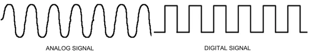
Analog and Digital Signal
- Analog Signal – Signal is defined as a sine wave. This signal is measurable and controllable through the complete cycle of high and low peaks. Specific adjusting screws allow individual system adjustments.
- Digital Signal – Signal is defined as a square wave. Inputs and outputs from the controller are in two states:
- OFF – 0 to 2.5 VDC
- ON – 2.6 to 5.0 VDC
If facility requirements dictate the need to interface analog signal(s) with digital signal(s), an inverter can be installed to change a digital signal to an analog signal. A converter can be installed to change an analog signal to a digital signal.
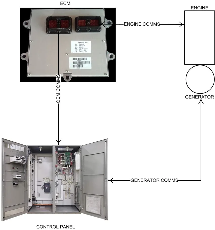
ECM
This example illustrates the interface between the components of a generator set that has advanced engine controls but relies on external communications from an external control panel. The flow example below was designed using information from a Cummins QSK45/60 Industrial Wiring Diagram. Component definitions are as follows:
- ECM – Receives input signals and transmits output signals to the engine. Receives input signals from the control panel.
- Engine – Generator prime mover. Receives input signals and transmits output signals to the ECM.
- Control Panel – Receives input signals from the generator and transmits output signals to the ECM.
The engine ECM is the heart of the engine control. It completes the information loop between the engine, generator, and control panel. Digital and analog data transferred between these components is either input or output. Examples include:
- Engine Transmit to ECM – Engine speed, temperature, coolant sensor, fuel pump, timing rail, and fuel rail pressure.
- ECM Transmit to Engine – Engine start, fuel shutoff, fuel and timing rail actuators, and fan clutch.
- Generator Transmit to Control Panel – Generator supplies voltage to the control panel for distribution.
- Control Panel Transmit to ECM – The control panel houses customer-supplied components.
Signals are transmitted to the ECM for throttle adjustments to maintain speed requirements.
Communication Process During Power Failure
- Start signal sent from the control panel (via automatic transfer switch) through the ECM to the engine.
- Engine starts. ECM monitors engine functions and adjusts fueling to achieve preset engine speed. ECM can shut the engine down during critical engine failures.
- Generator sends voltage to the control panel for distribution. Many control panels can monitor generator operating statistics.
- Primary power is restored. The control panel transmits the engine stop signal to the ECM. The ECM transmits the shutdown signal to the engine.
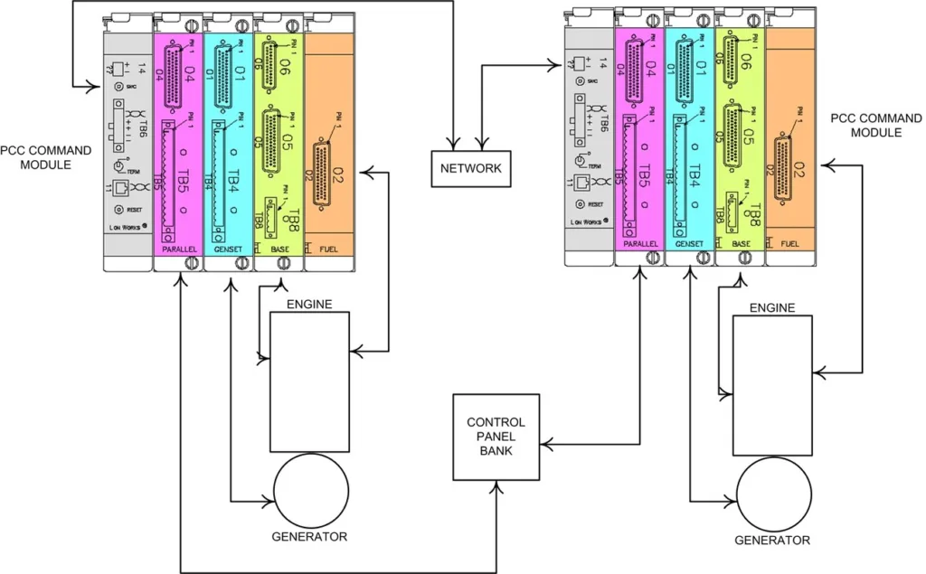
Engine and Generator Interface Controls
Newer generator models were introduced with full monitoring and control hardware and supporting software. Modules for paralleling capability were added. This arrangement can be set up redundantly for critical emergency power supplies. If one generator fails, the load is reduced, and the other continues to support the load.
In the example below, two generators powered by Cummins QSK45 generators are used. The control system used is PCC 3200. The individual modules of the unit are used for:
- Fuel (Connector 02) – Communicates with input and output engine fuel system components.
- Base (Connectors 05 and 06) – Communicates input and output base engine function components.
- Generator (Connector 01) – Communicates input and output signals with the generator.
- Parallel (Connector 04) – Allows paralleling of multiple generators.
- TB6 – Networking card. Allows network capability for each generator on the network.
The sequence of events during a power failure is conducted under the basic concepts mentioned in the above ECM section. Key differences include:
- All generator hardware and software are contained in one operating system.
- Capable of paralleling multiple generators.
- Advanced monitoring and reporting capabilities.