
Relays play a crucial role in controlling electrical circuits in generators, allowing for automation and protection in various systems. Below is an overview of the different types of relays used in generator systems, their functions, and their specific applications.
Electromagnetic Relays
Electromagnetic relays use electrical signals to control circuits and can manage multiple circuits using a single electrical supply. They are used to switch higher power outputs based on low-power inputs.
Key Components:
- Poles: Each relay has poles that can be either Normally Open (NO) or Normally Closed (NC). The poles are the contacts that open or close when the relay is energized.
- Throws: Refers to the number of contacts that change when the relay is activated. A single throw means one contact, while double throw involves two contacts that open and close.
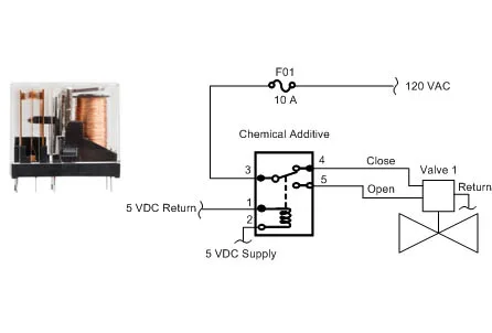
Sequence of Operation Example: In a water treatment system:
- A low voltage (5 VDC) signal is sent to energize the relay.
- The relay changes the state of the contact, opening and closing different points in the circuit.
- This operation controls a valve that opens and closes, allowing chemical additives to flow based on the relay’s action.
Applications:
- Used in control panels where they act as an interface between controllers and components like motors or solenoids.
- Commonly used in systems where multiple circuits need to be controlled by a single signal.
Relay Logic Circuits
Relay logic circuits use a combination of relays to implement basic logic operations like AND, OR, and NOR gates. These circuits are the building blocks of more complex automation systems and are common in older industrial equipment.
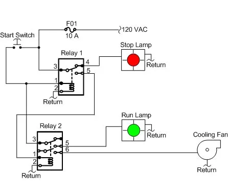
Example: A basic control circuit to start and stop a cooling fan:
- The system is powered, and a relay energizes the circuit to illuminate a Stop Lamp.
- Pressing the Start switch energizes Relay 1, which switches contacts to extinguish the Stop Lamp and close new contacts.
- Relay 2 is activated, and the cooling fan starts while the Run Lamp lights up.
- Pressing the Start switch again reverses the relay states, stopping the cooling fan and illuminating the Stop Lamp.
Advantages:
- Simple to implement for controlling basic systems.
- Easy to troubleshoot with fewer components involved.
Disadvantages:
- Complex logic circuits can be difficult to troubleshoot due to interdependencies between relays.
Solid State Relays (SSR)
Solid State Relays (SSRs) are similar to electromagnetic relays but lack moving parts. These relays use semiconductor components to perform switching operations.
Advantages:
- No Moving Parts: SSRs have no mechanical parts, leading to a longer lifespan and no risk of contact wear.
- Silent Operation: Unlike electromagnetic relays, SSRs operate silently.
- Durability: They are more resistant to shock, vibration, humidity, and magnetic fields.
- Applications in Hazardous Environments: Since SSRs don’t spark, they are safe to use in explosive environments.
Disadvantages:
- Heat Generation: SSRs can generate heat when in the closed state, unlike electromagnetic relays.
- Lower Resistance When Open: SSRs may experience some reverse leakage, which can be problematic for certain applications.
- Polarity Sensitivity: Some SSRs have circuits that are sensitive to polarity, unlike their electromagnetic counterparts.
Applications:
- Common in control panels where space is limited and silent operation is required.
- Ideal for controlling LED lights and low-voltage electronic devices.
Summary
Relays are integral to the functioning of generators and industrial control systems, enabling automation and protection of critical components. Understanding the differences between electromagnetic relays, relay logic circuits, and solid-state relays is crucial when designing or maintaining power systems. Each type offers distinct advantages and is suited to specific tasks within a generator’s control system.
For generator and control system needs, consulting with an expert can help in selecting the right relay for optimal performance and reliability.