
Monitoring Engine and Generator Set
Generator Set Monitoring
Many options are available to allow facilities managers or owners to monitor and interface with standby or primary power generator sets. Monitoring engine parameters helps in the early diagnosis of developing problems, allowing for repairs before they lead to shutdown failures, which raises the reliability of both emergency and primary power systems. Basic configurations outlined below:
Historic Generator Sets
The basic theory of operation for a diesel engine remains unchanged. Historic generator sets often have low hours and are reliable, but they may be replaced due to the inability to supply advanced information to facilities managers. If facility requirements do not require advanced alarm and monitoring systems, historic generator sets are a viable solution. Aftermarket monitoring and control systems can be employed to monitor and control basic engine and generator functions.
Basic Engine and Generator Monitoring Functions:
- Engine oil pressure
- Engine coolant temperature
- Engine RPM (Revolutions per Minute)
- Generator voltage
- Generator amperage
- Compartment louver position and control (depending on hardware manufacturer)
- Compartment temperature (depending on hardware manufacturer)
Aftermarket Monitoring Options
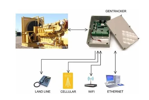
Aftermarket suppliers can be used to monitor single or multiple generator applications. These products comply with SAE (Society of Automotive Engineers) and other state and government agencies. One option is the Gen-Tracker generator monitoring system, which can monitor the following:
- Monitor three voltage sensor inputs (Normal, Emergency, and Load)
- Four digital sensor inputs (oil pressure, coolant level, low fuel pressure, high coolant temperature)
- Engine starter contact status
- Fail to exercise with software alerts
- Battery condition monitoring
- Remote starts and generator status
Panel Considerations
When selecting a generator monitoring system, consider the following:
- Monitoring system capabilities – Will the system meet all current and future communication needs?
- Digital input points – These are switches that are either in an ON or OFF state, such as pressure switches.
- Fuel tank level monitor selection – Options include 5 to 20 V and 4 to 20 ma, with the latter being more accurate.
Circuit Card Monitoring
A sample of a circuit card helps technicians quickly determine if the system is operating correctly. Key indicators include:
- DS1 COM – Indicates unit communication with device (phone, network, etc.)
- DS2 SIGNAL – Unit waiting to transmit signal
- DS3 FAULT – Indicates generator fault
- DS4 HEARTBEAT – Indicates unit is functioning correctly
- DS5 SPEED – Network speed indicator
- DS6 LINK – Indicates linked to network
- DS7 START CONTACT – Indicates starter contact status
- DS8 RELAY STATUS – Indicates relay status (energized or de-energized)
ECM Controlled Engines without Advanced Control Panels
Control Panel Capabilities
The ECM (engine control module) is a significant advancement in diesel engine technology. It controls all engine functions via software and hardware, which include input and output devices. The ECM allows for advanced monitoring functions, which can be accessed using a laptop connected to a 9-pin data link connector.
Key Features of ECM-Controlled Engines:
- Input devices – Devices that provide signals such as temperature, pressure, speed, and position.
- Output devices – Devices controlled by the ECM, such as engine starters and lights.
For remote monitoring of engine and generator functions, an additional control panel must be used.
Choosing the Right Control Panel
When selecting a control panel for ECM-controlled engines, consider the following:
- J1939 connections and software for monitoring engine functions
- OEM harness availability for different manufacturers
- Included mounting hardware and cables
- Installed software packages
Example Configuration with P10 Control Panel
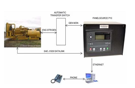
The Panelsource P10 CAN BUS is an example of a control panel that integrates both engine and generator monitoring functions. Key features include:
- Connections to automatic transfer switches
- J1939 Datalink for alarm monitoring and ECM access
- Ethernet and phone connectivity for remote communication
ECM Controlled Engines with Advanced Control Panels
Generators Operating in Parallel
ECM-controlled generators with advanced control panels offer many capabilities. These include:
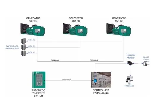
- Redundant supply configuration for emergency generators
- Advanced monitoring via SAE J1939 datalink
- Remote annunciator monitoring for operators
- Load sharing capabilities and manual paralleling of load is not required
- System computer interface with remote monitoring via cell phones and smart devices.