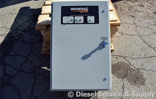
An Automatic Transfer Switch (ATS) is designed to transfer power from a utility grid to a backup power source, typically a generator, in the event of a power failure. The control system within an ATS is what enables the transfer process to happen automatically without human intervention. Below is an explanation of how this control system functions.
Utility Power Supply and ATS Role
- Normal Power Supply: Under typical conditions, power is supplied by the utility grid.
- ATS Function: When the primary power source fails, the ATS facilitates the automatic transfer of power to a backup generator. This transition happens seamlessly, ensuring the application or facility continues to operate without interruption.
Control Panel and Automation
The control panel is the heart of the ATS system, making it “automatic.” It monitors the power supply and takes action when a power failure is detected:
- Power Failure Detection: The control panel detects a drop in voltage or complete failure of the normal power supply, using sensors to monitor all phases of the power supply.
- Generator Start: Upon detecting a failure, the control system sends a signal to the generator to start up. The generator must reach the required voltage and frequency before the control panel signals the ATS to switch to generator power.
Key Functions of the Control Panel
- Voltage and Frequency Sensing:
- The control panel constantly monitors the power supply’s voltage and frequency. If they fall below preset thresholds, it triggers the generator to start.
- It ensures that the generator is capable of accepting the load by confirming the generator’s voltage and frequency levels meet the necessary specifications.
- Time Delays:
- Time delays are essential to avoid false transfer during brief outages or power fluctuations. Three key types of delays are typically employed:
- Transfer Delay: Prevents unnecessary switching during short interruptions. This delay typically lasts 0-6 seconds, with 1 second being the most common.
- Return Delay: After the generator has been in operation, this delay ensures the return to the normal power source only when the grid power is stable. This can range from 0 to 30 minutes.
- Cool Down Delay: Ensures the generator runs unloaded for a period before shutting off after a power failure ends.
- Time delays are essential to avoid false transfer during brief outages or power fluctuations. Three key types of delays are typically employed:
- Engine Control Contact:
- The control panel has a contact point that signals the generator’s engine to start when the normal power supply fails. This is typically a dry contact that completes a circuit to the generator’s cranking batteries.
- The circuit is opened when the generator needs to shut down after normal power is restored or after the engine has cooled down.
- Regular Testing and Maintenance:
- To ensure reliable operation, the ATS control system should undergo regular testing.
- This includes manually simulating power failure to verify that the transfer switch and generator startup processes work as expected.
- Control systems are designed to meet industry standards, but specific systems may vary depending on the application.
- Backup Contact Points:
- For redundancy, some ATS systems have backup contact points in case of failure in the primary contact. This ensures reliable engine start and stop functions.
Time Delay for Load Sequencing
- In some cases, the user may require a specific sequence for transferring loads to the backup generator. The control system can incorporate an adjustable time delay for each transfer switch, allowing the loads to be transferred in the desired order.
Conclusion
The control system of an ATS is critical for ensuring that power transitions seamlessly from the utility grid to a generator when required. Its functions include voltage and frequency monitoring, time delays, engine start/stop control, and regular testing, all contributing to the reliability and efficiency of emergency power systems.